What Is a Hot-Swappable Keyboard? Compatibility and Switch Replacement
See how hot-swap sockets work, check which switches fit, and follow a switch replacement from removal to testing. Compare soldered builds, socket durability, and Mill-Max conversions.
1. What is a hot-swappable keyboard?
A hot-swappable keyboard lets you remove and replace compatible switches without desoldering their terminals each time. That makes it practical to try a different spring weight, change from tactile to linear, fit quieter switches, or replace a failed switch. The first purchase check is whether the exact keyboard you are buying has hot-swap support and which replacement switches it accepts.
Inside a conventional mechanical switch, pressing the stem operates electrical contacts. Two metal terminals carry that connection to the keyboard’s circuit board, or PCB. In a soldered build, solder joins those terminals directly to the board. In a hot-swap build, the terminals slide into contacts inside a socket. Pulling out the switch releases the terminals from those contacts.
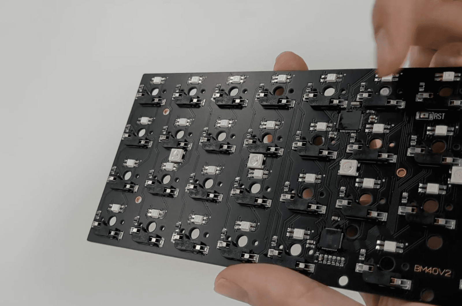
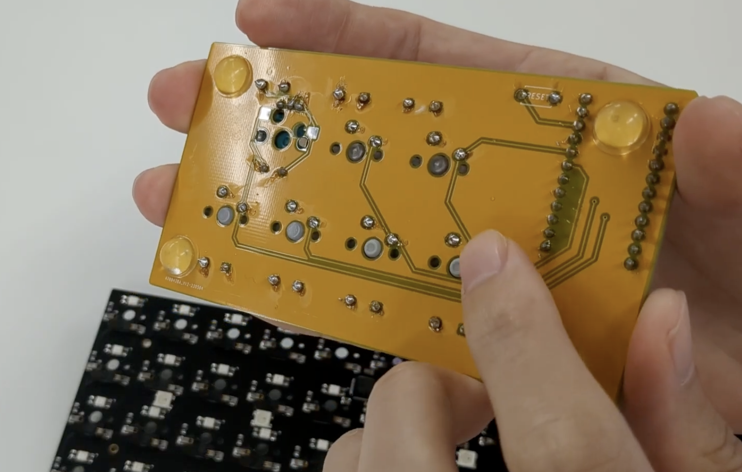
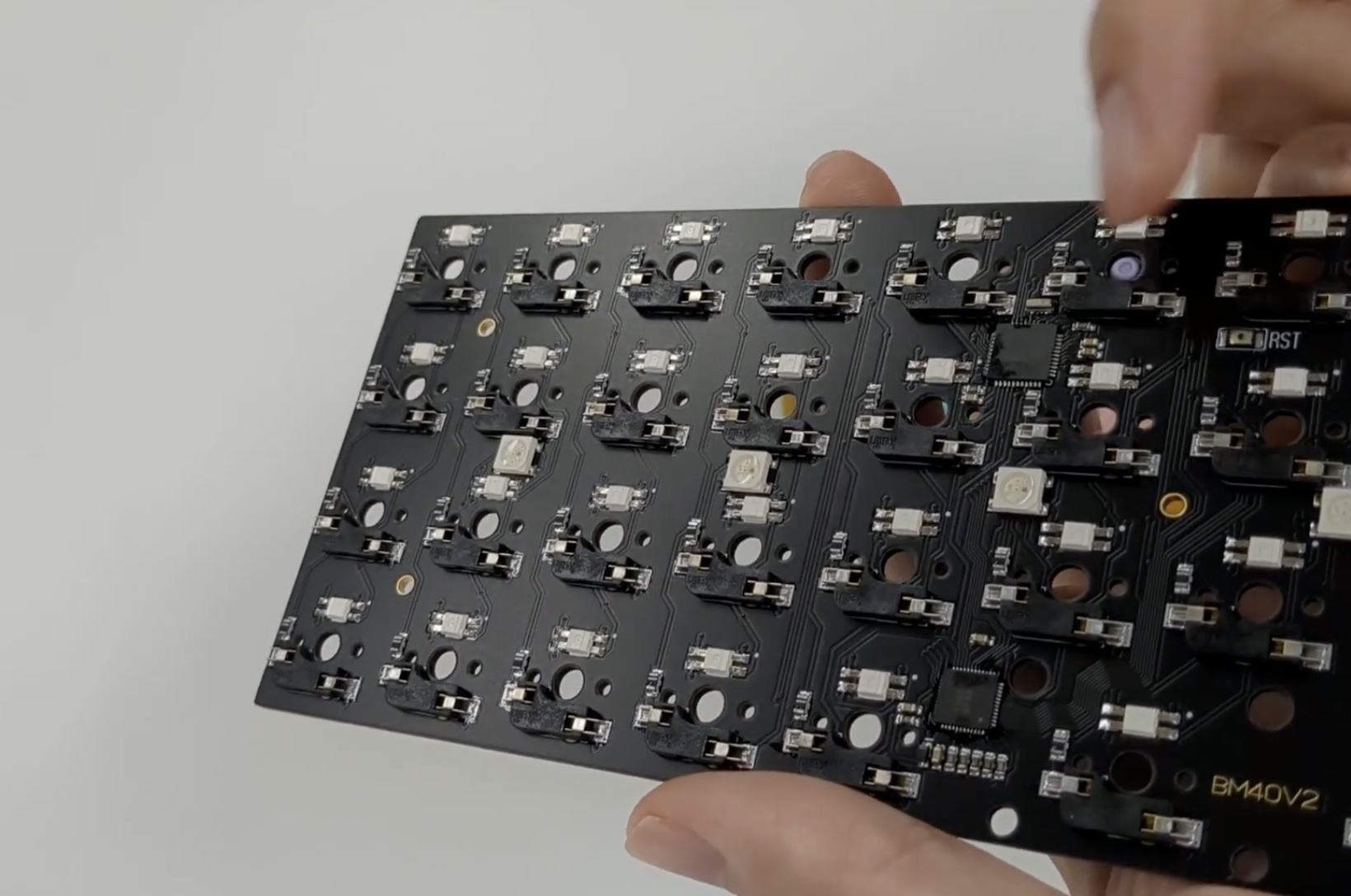
The socket itself is soldered to the PCB. You can see the small attachment points at the ends of the black socket bodies in the BM40V2 photograph. The switch comes out while the socket stays on the board. On the gold-colored PCB, the visible solder joints show the other approach. Look at the pairs of switch-terminal joints as well as the other electronic connections on the board.
The difference matters when you decide how much experimenting you want to do. A removable switch lets you try a few candidates before buying enough for the whole board. A soldered build gives you a fixed connection once you have chosen your switches and layout. Both approaches can be part of a carefully assembled keyboard. This guide starts with identifying your board, then follows compatibility, replacement, and the longer-term choice between them.
2. How can I tell if my keyboard is hot-swappable?
Find the full model name and the option selected on your receipt or order confirmation. Then look for hot-swappable in the manufacturer’s specifications for that option. A product family can include soldered and hot-swap versions, and the difference may appear in a backlight or switch selector. Save the specification for your version so you can check it again when shopping for replacements.
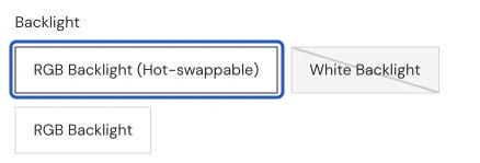
The Keychron K3 Max selector in the Low-Profile Mechanical Keyboard Guide is a useful example. The photographed selector explicitly labels one option RGB Backlight (Hot-swappable). Reading the family name alone leaves out the option that determines whether the switches can be removed. Look for an equally explicit statement on your own keyboard’s listing or manual.
Removable keycaps give you access to the switch top. The connection you need to identify is underneath the switch, so start with the documentation before applying a switch puller. If the documentation is unclear, ask the keyboard manufacturer about the exact model and revision. For a kit with an exposed PCB, its labeling and build guide can also help identify the connection.
Once hot-swap support is confirmed, record the supported switch family. A specification such as 3-pin and 5-pin MX mechanical switches is much more useful than a general customization claim. The next step is checking the replacement against that specification.
3. Which switches will actually fit?
Start with the switch technology and profile, then check the pins, housing, and keyboard’s compatibility list. Hot-swap describes the ability to remove a switch. The board’s sockets and electronics determine the replacements it can use. A cross-shaped keycap stem gives you one piece of the keycap interface, while the underside of the switch supplies the information you need for the PCB.
For conventional MX-style switches, a 3-pin version has two metal electrical terminals and a central plastic locating post. A 5-pin version adds two plastic locating posts. A PCB and plate designed to support both can accept either version. A 3-pin-only board needs a separate fit check for a 5-pin switch. Clipping the extra plastic posts is an irreversible modification, so choose a supported switch version when possible and confirm the keyboard maker’s instructions before modifying parts.
Profile also matters. Low-profile switches can use different contact positions, center openings, locating posts, socket designs, and plate clearances. The Low-Profile Mechanical Keyboard Guide compares specific Kailh Choc and Gateron generations with manufacturer drawings. Use that guide when the keyboard’s listing names a low-profile family, then verify the exact switch SKU against the board’s supported replacements.
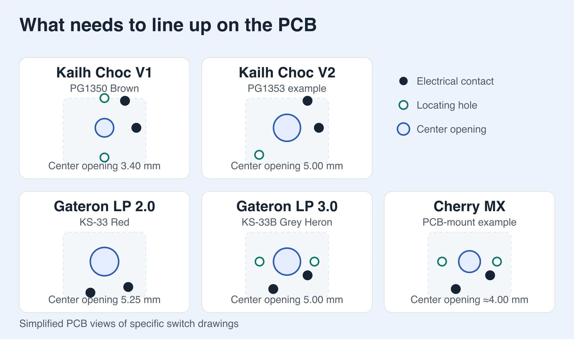
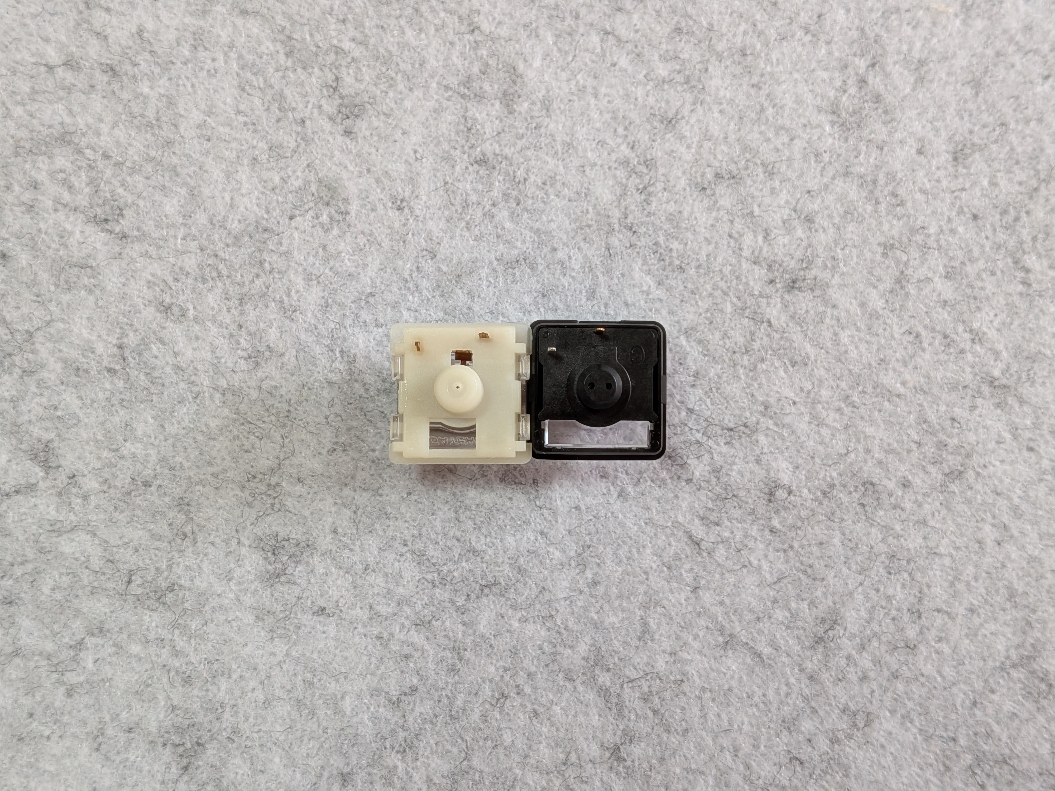
The diagram below aligns the switch orientations to compare the recommended PCB hole patterns for five specific examples. Follow the two electrical contact positions, then the center opening and locating holes. The photograph underneath shows two real low-profile switches from the underside, with Gateron on the left and Lofree on the right. Compare the metal terminals, central post, and housing outline, then match the exact switch to the keyboard’s supported parts.
Optical and magnetic boards need their own checks. The sensor system and firmware have to support the replacement. Even within magnetic switches, the magnet arrangement and keyboard generation can matter. Keychron’s compatibility guide includes hybrid keyboards designed for both conventional mechanical switches and specified magnetic families. Follow the compatibility list for that exact model when considering one of those boards.
Finally, check the complete assembly. The switch should seat in the plate, the pins should align with the socket, and the keycap should clear the housing through its travel. Buy a small sample if you are choosing an unfamiliar family. Test it in the intended board before ordering a full set, especially when the manufacturer names a limited list of compatible switches.
| Your keyboard’s specification | What to confirm | Useful evidence |
|---|---|---|
| MX-style mechanical, 3-pin and 5-pin support | The replacement’s terminals, housing, and plate fit | Keyboard specifications and switch drawing |
| MX-style mechanical, 3-pin support only | Supported replacement version and locating-post clearance | Exact PCB or keyboard instructions |
| Low-profile mechanical | Named family, generation, and complete assembly fit | Manufacturer compatibility list and drawings |
| Optical | Supported optical switch family | Keyboard maker’s replacement list |
| Magnetic or hybrid | Supported sensor and switch combination for that revision | Model-specific compatibility list |
4. How to replace a switch, step by step
Prepare a keycap puller, a suitable switch puller, good lighting, and a replacement whose compatibility you have checked. Start with one ordinary letter key. This keeps the first attempt simple and gives you a working example before you change the whole board. Keep the removed keycap and switch together so you can return to the original setup.
Turn the keyboard off and unplug its cable. For a wireless board, switch off the keyboard as well as disconnecting USB. Follow the manufacturer’s battery and disassembly instructions if you are building a kit. Pull the keycap upward with the keycap puller, taking care around neighboring keys. A large stabilized key has additional parts underneath, which is another reason to begin with a letter.
Use the switch puller on the retaining clips specified by the switch or keyboard instructions. Compress the clips and lift the switch evenly. Pay attention to resistance and check that both clips are released. If it catches, stop and inspect the grip, the plate, and the model’s removal instructions. Pulling harder while the switch is still caught puts unnecessary load into the assembly.
Inspect the replacement’s two metal terminals before inserting it. They should be straight and aligned with the socket openings. Check the orientation against the removed switch, the center post, and any locating holes. Lower the switch squarely into the plate and PCB, keeping its terminals aligned. On an exposed kit PCB, support the back of the socket as directed by the build guide while pressing the switch into place.
Confirm that the housing is fully seated and clipped into the plate. Flexible plates can sag during insertion. Mode’s guide specifically calls attention to seating with softer materials such as PP, POM, PC, and nylon. In a preassembled keyboard, use the maker’s installation method. When resistance feels wrong, remove the switch and inspect its pins before trying again.
Reconnect the keyboard and test single presses, held input, and repeated presses in a key tester or a text field. VIA’s tester is useful on supported boards. Then reinstall the keycap and check its full travel, return, and clearance against adjacent caps. Once that first key works reliably and feels right, continue in small groups, testing each group before replacing more switches.
5. What if the new switch does not work?
Begin with the position you just changed. Turn off and disconnect the keyboard again, remove the switch, and inspect both metal pins. A pin can fold underneath the housing instead of entering the socket. Compare it with a straight, unused switch. A damaged terminal may need careful straightening or replacement of the switch, depending on its condition.
Next, check whether the housing had seated fully. Inspect the plate opening, orientation, and any locating posts. If the board has a configurable keymap, verify the assignment for that position too. Testing several nearby keys can help establish whether the problem is confined to one switch position or affects a larger part of the keyboard.
A known-working, compatible switch can help narrow the problem. Test it in the affected position, then test the suspect replacement in a working position if its pins are undamaged. A problem that follows the switch points toward the switch. A problem that stays at one position calls for checking the socket, board, and configuration.
Intermittent input or a key that works only under extra pressure can indicate a poor connection. ZSA’s repair examples show loose and detached sockets. If inspection reveals a moving socket or damaged PCB attachment, stop inserting switches at that position and use the manufacturer’s support or repair route. Repairing the connection requires assessing the socket and pads. The life rating printed for a socket cannot describe damage caused by a single misaligned insertion.
6. Hot-swap vs. soldered builds in sound and feel
I tend to prefer the sense of solidity in a soldered build. To my ears and fingers, it can have a more unified sound and a steadier feel under the key. That preference is part of why I still consider soldering after settling on switches I enjoy. Hot-swap is especially useful during the stage when I want to keep trying different options.
There is a physical difference behind that comparison. Solder joins the switch terminals directly to the PCB, adding fixed connections between the switch and board. A hot-swap socket uses removable contacts. As a structural inference, a direct soldered connection can help constrain movement of the switch housing. How much that changes a particular assembled keyboard depends on the fit and support elsewhere in the build.
The plate opening, retaining clips, locating posts, and seating all matter when judging stability. A key also has several places where movement can occur. The whole switch housing can move relative to the plate or PCB, while the stem can move inside its housing. Soldering the electrical terminals addresses the connection to the board. The switch’s internal tolerances continue to influence stem movement.
For sound, listen to the entire assembly. PCB thickness and flex cuts, the plate, the mount, foam, switches, and keycaps all affect the result. Mode’s Sonnet instructions even note that the optional standoffs may influence the sound profile. When a solder PCB and a hot-swap PCB also differ in thickness, cuts, or mounting hardware, the comparison includes those changes too.
My preference for a solid-sounding soldered build is a qualitative impression from using keyboards. For a focused comparison of the connection itself, keep the case, plate, switches, caps, mounting, key position, and recording setup as consistent as possible, and record the PCB differences. A clearly described build gives the reader more to work with than an acoustic promise based on the connection label alone.
A switch swap offers a separate, practical way to change the result. Below, the same Flow Lite 2 84 is recorded with Echo and then Void silent linears. This low-profile example lets you hear a switch change within one board. Listen for the initial impact, the return, and any metallic ring between presses. The Flow Lite 2 review describes the fit and the reviewer’s experience in more detail.
For choosing the replacement, the Linear Switch Guide, Tactile Switch Guide, and Silent Switch Guide explain the differences you can explore. Try a few candidates under the keys you use most, with the same keycaps, before replacing the full set. The Keyboard Switch Sounds Guide can help you describe the part of the sound you want to change.
7. How long do hot-swap sockets last, and what is Mill-Max?
Repeated insertion and removal is a mechanical task for the socket’s contacts. Manufacturers publish durability specifications for particular parts. Check the actual socket model and specification revision when a keyboard maker gives you that information. The table below includes the complete part numbers from the documents checked for this guide.
The older Kailh CPG151101S11 specification lists 100 cycles and a life test of at least 100 cycles. Kailh’s CPG151101S11-16 document lists 5,000 cycles and a minimum 5,000-cycle life test. The two documents also use different contact-resistance acceptance limits in that test. Read the rating together with its conditions when making a comparison.
Treat these as specified test figures. Actual service life depends on the contact pairing, handling, and installation. A worn contact and a socket detached from its PCB are different problems. Bent pins or unsupported insertion can damage an assembly before its nominal cycle figure. The BM40V2 photograph shows the socket arrangement, but it does not establish the installed socket’s precise part number or rating.
Mill-Max is a connector manufacturer. In keyboard building, a Mill-Max conversion usually means soldering small individual receptacles into the switch-terminal holes of a compatible solder PCB. Each receptacle accepts one switch terminal. A conventional MX-style switch therefore uses two sockets, one for each metal terminal. Once they are installed correctly, compatible switches can be inserted and removed.
Common keyboard socket families include 0305, 7305, and 3305. Their dimensions and finishes vary. Keebio’s guide shows how shoulder height above the PCB and tail length below it affect fitting and installation. Check the finished PCB hole diameter, case clearance, switch seating, and terminal shape before selecting a part. Some wider switch terminals are difficult to fit into these receptacles.
The two specific Mill-Max parts in the table are rated for at least 1,000 cycles. That exceeds the older Kailh document’s cycle figure. The 5,000-cycle Kailh example also shows why a brand-wide durability ranking needs more information. Mill-Max explicitly says mating-pin size, shape, finish, and application-specific variables affect receptacle life. These documents provide component specifications under their respective conditions.
A conversion requires soldering skill and compatible board geometry. It can be attractive when a solder PCB offers a layout you want and you still expect to change switches. Budget for the individual sockets and the installation work, and confirm the exact fit first. An existing surface-mount hot-swap footprint and a solder PCB’s terminal holes use different mounting arrangements. Choose parts for the PCB design you are actually building.
| Part and document | Published cycle figure | Context |
|---|---|---|
| Kailh CPG151101S11, revision B (2016) | 100 minimum in the life test | Older manufacturer specification |
| Kailh CPG151101S11-16 (2022) | 5,000 minimum in the life test | Different part suffix and test acceptance limits |
| Mill-Max 7305-0-15-15-47-27-10-0 | 1,000 minimum | Mechanical life for this receptacle |
| Mill-Max 3305-1-15-15-47-27-10-0 | 1,000 minimum | Life varies with mating pin and application |
Figures are from each manufacturer’s specified test conditions. They describe insertion/removal durability of the named socket or receptacle. Check the installed part and PCB assembly when evaluating a keyboard.
8. What to check before buying replacement switches
Choose the change you want first. A quieter shared desk, a lighter press, a stronger tactile bump, and replacing one failed key call for different candidates. Use Keebpedia’s switch catalog to narrow the choices, then verify fit against the keyboard maker’s documentation. Keebpedia’s keyboard catalog can help you keep track of the board and variant you are comparing.
If you expect to experiment, a supported hot-swap setup makes those comparisons convenient. If you have settled on your switches and value the fixed connection and feel of a soldered build, include soldering and later repair work in that decision. For a Mill-Max conversion, add socket dimensions and installation to the plan. Keep the original working switches until the replacements have passed testing and you have spent time typing on them.
- Confirm the complete keyboard model, revision, and selected hot-swap option.
- Match the switch technology, profile, pin layout, and supported family.
- Count the switch positions and keep a few compatible spares for testing.
- Prepare the correct pullers and follow the manufacturer’s installation method.
- Check the socket part number and published durability when available.
- Try a small sample, test input and return, and compare the feel before committing to a full set.